Popular in your industry


Top categories
Pumps & Parts

Tool Storage
Fasteners
Welding & Soldering Supplies
Pneumatic Tools
Hardware
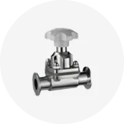
Valves

Abrasives

Garden Tools

Hydraulic Tools
Machining
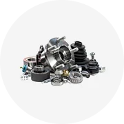
Tool Parts
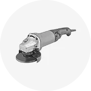
Power Tools
Power Tool Accessories

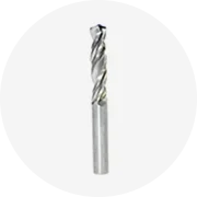
Drill Bits
Hand Tools
About products and suppliers
Understanding Flanged Gate Valve CAD Drawings
Flanged gate valves are integral components in various industrial systems, controlling the flow of liquids, gases, and slurries. The flanged gate valve CAD drawing is a detailed blueprint that provides specifications for manufacturing and assembly. These drawings are crucial for engineers and technicians to understand the intricate details of gate valves, ensuring proper fit and function within complex piping systems.
Types and Applications of Flanged Gate Valves
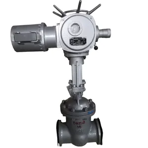
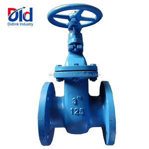
There are multiple types of flanged gate valves, each designed to meet specific operational requirements. These include rising stem, non-rising stem, and knife gate valves. The applications of these valves are diverse, ranging from wastewater treatment to petrochemical processing. The gate valve design depicted in CAD drawings allows for precise production, catering to the demands of high-pressure and temperature environments.
Features and Materials
A flanged gate valve is characterized by its robust design, which typically includes a flat closure element and flanged ends for easy installation. The materials used in manufacturing, such as stainless steel, cast iron, or PVC, are detailed in the valve CAD drawing. These materials are selected based on their durability, corrosion resistance, and compatibility with the media they control.
Advantages of Detailed CAD Drawings
The precision of a flanged gate valve drawing ensures that all components are accurately represented, reducing the risk of errors during fabrication. This level of detail supports quality control processes and aids in the maintenance and repair of the valves, extending their service life and reliability.
Selection and Customization
While selecting a flanged gate valve, it is essential to refer to the gate valve CAD to ensure the specifications meet the system's requirements. Customization options, although not directly offered on Alibaba.com, can be discussed with suppliers, who can tailor valves to unique operational needs based on the detailed CAD drawings.
Integration in Piping Systems
Integrating a flanged gate valve into an existing system requires careful consideration of the valve's CAD drawing. This ensures compatibility with the piping dimensions and the functionality required for the application. The CAD drawing serves as a guide for proper installation and operation, contributing to the overall efficiency and safety of the industrial system.

Trade Assurance
Source on Alibaba.com
Sell on Alibaba.com


 浙公网安备 33010002000092号
 浙B2-20120091-4